Pages: [1] 
|
 |
|
|
 Author
|
Topic: Antenna Tuning Circuits (Edit on 17.Jan.25) (Read 1120 times)
|
|
LEO73
Neuling

 Offline Offline
Posts: 10

<Never a joy>

|
 |
Antenna Tuning Circuits (Edit on 17.Jan.25)
« on: 31. December 2024, 17:11:31 »
|
|
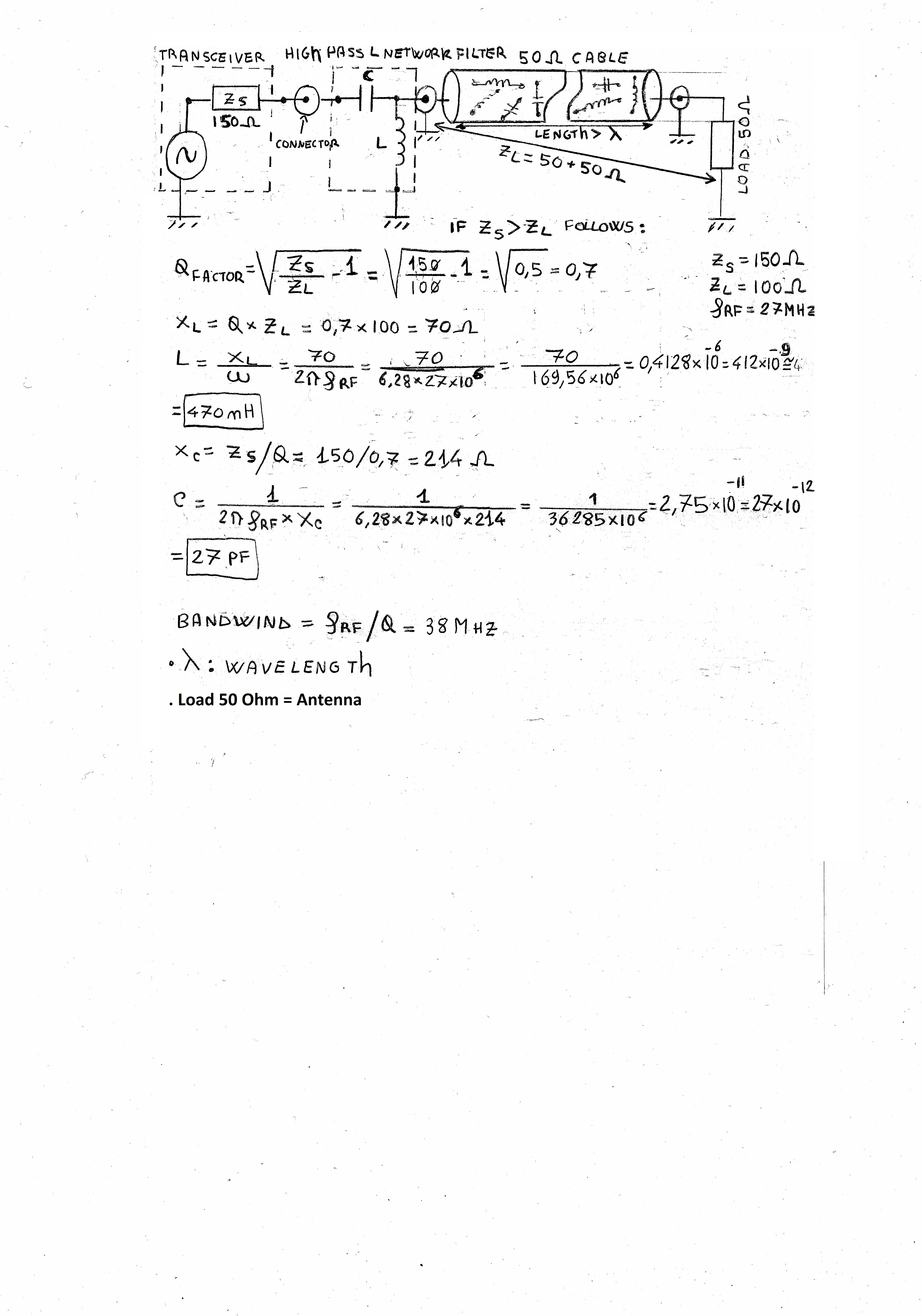
| If the RF cable length is major of wavelength (λ) we can consider a 50 Ohm cable as a Network connections (inside there's more inductances and capacitors) |
|
What is an Antenna tuning?
It is a passive circuit made using Inductances and capacitors, this circuit permit to make the transceiver output load equal to the antenna load; in fact we would have the maximum power transfer (between transceiver and antenna) when the transceiver output capacitive-inductive reactance is equal to the antenna capacitive-inductive reactance.
EDIT 17.JAN.2025 (sorry for previous uncomplete versions)
The manual says that the McHf transceiver works well with antennas that have an impedance of 50 Ohm. I deduce that in this case the output inductance of the transceiver is around 50 Ohm.
Usually:
If Transheiver Load is major than Antenna load you need a High-Pass-L-Network-Tuning
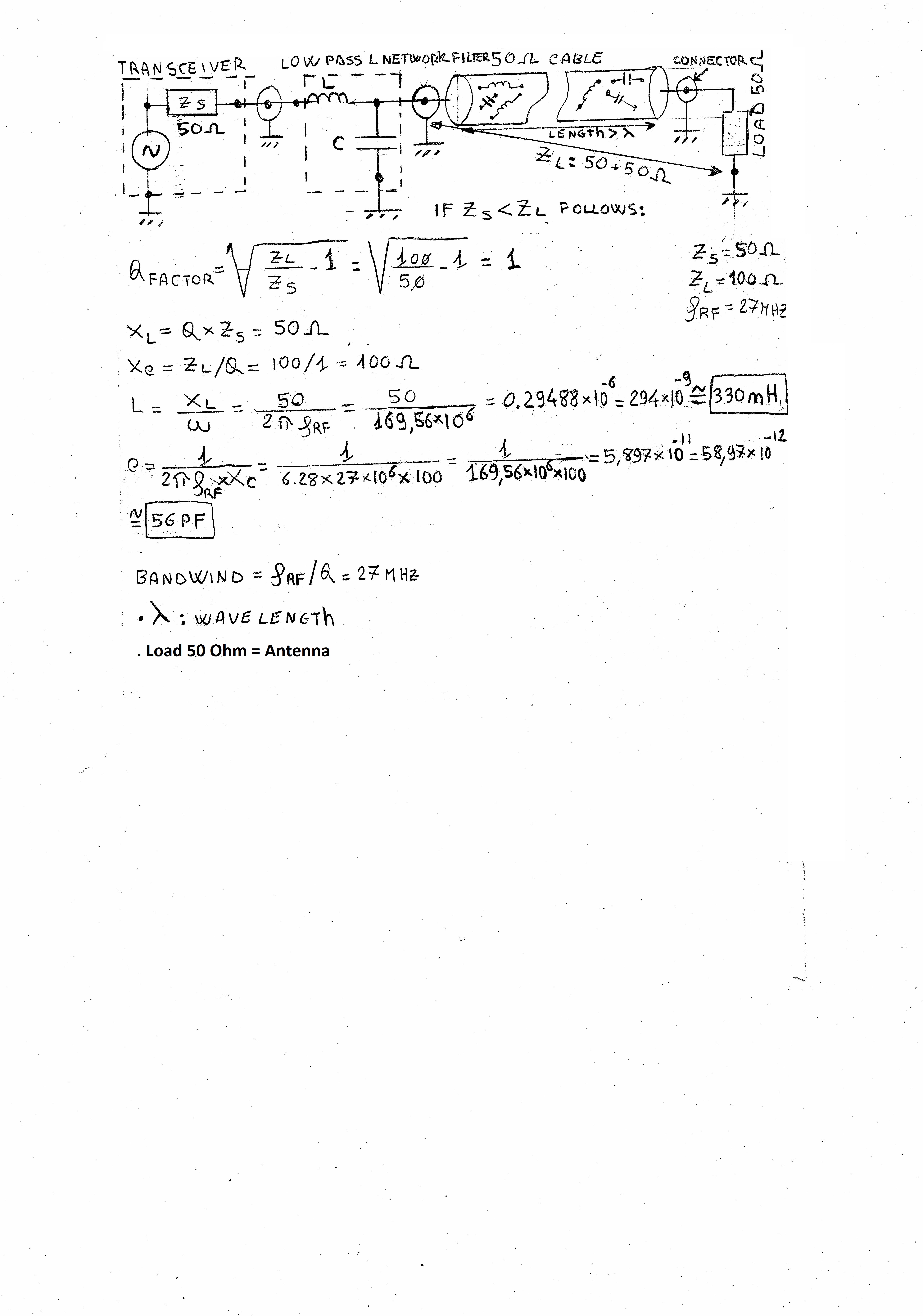
If Transheiver Load is minor than Antenna load you need a Low-Pass-L-Network-Tuning
|
|
Below there's an exercise that you can replicate for other frequencies:
NEVER A JOY
|

|
|
|
LEO73
Neuling

 Offline Offline
Posts: 10

<Never a joy>

|
 |
Re:Antenna Tuning Circuits
« Reply #1 on: 08. January 2025, 15:41:14 »
|
|
Edit on 16-Jan.2024 (sorry for previous uncomplete versions)
This is an opposite situation where Tranceiver Inledance in minor than Antenna Impedance, in this case we'll use a Low-Pass-L-Network Filter circuit.
Below calculation values:
 Never a Joy Never a Joy 
|

|
|
|
Pages: [1] 
|

|
|
|
|
|
|


