Author
|
Topic: Aufbaubericht OVI40-UI Platine Version 1.8 (Read 33010 times)
|
|
F4HTX
schon länger dabei

 Offline Offline
Posts: 66

Scotty, energize...

|
 |
Re:Aufbaubericht OVI40-UI Platine Version 1.8
« Reply #15 on: 10. January 2018, 14:20:23 »
|
|
Dear Friends,
Ready to power the UI board and...
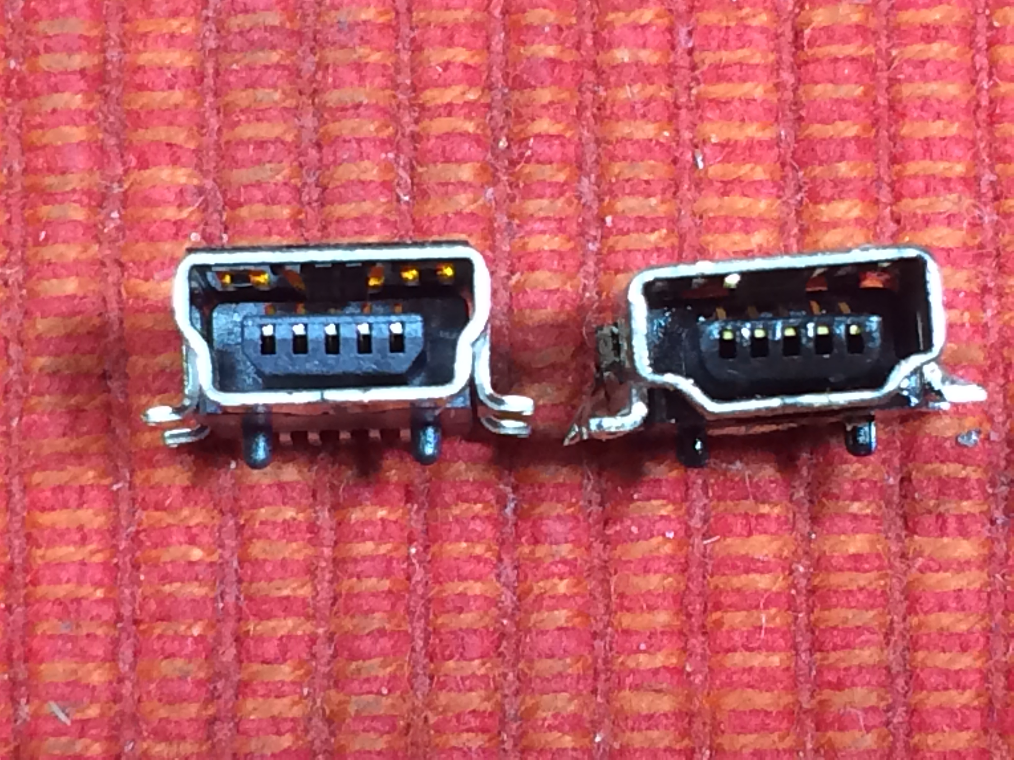
...the DFU USB plug didn't fit in !!!!
Please check urgently your USB DFU socket before soldering it, it my be defective as mine (cf. picture). Really strange...
You really do not want to experience unsoldering that thing 
I'll change that and come back with more info, Best Regards,
François
|
|
|
|
F4HTX
schon länger dabei
Offline
Posts: 66
Scotty, energize...
|
|
Re:Aufbaubericht OVI40-UI Platine Version 1.8
« Reply #16 on: 10. January 2018, 15:01:45 »
|
|
Dear Friends,
After changing the DFU socket, the Bootloader upload went well.
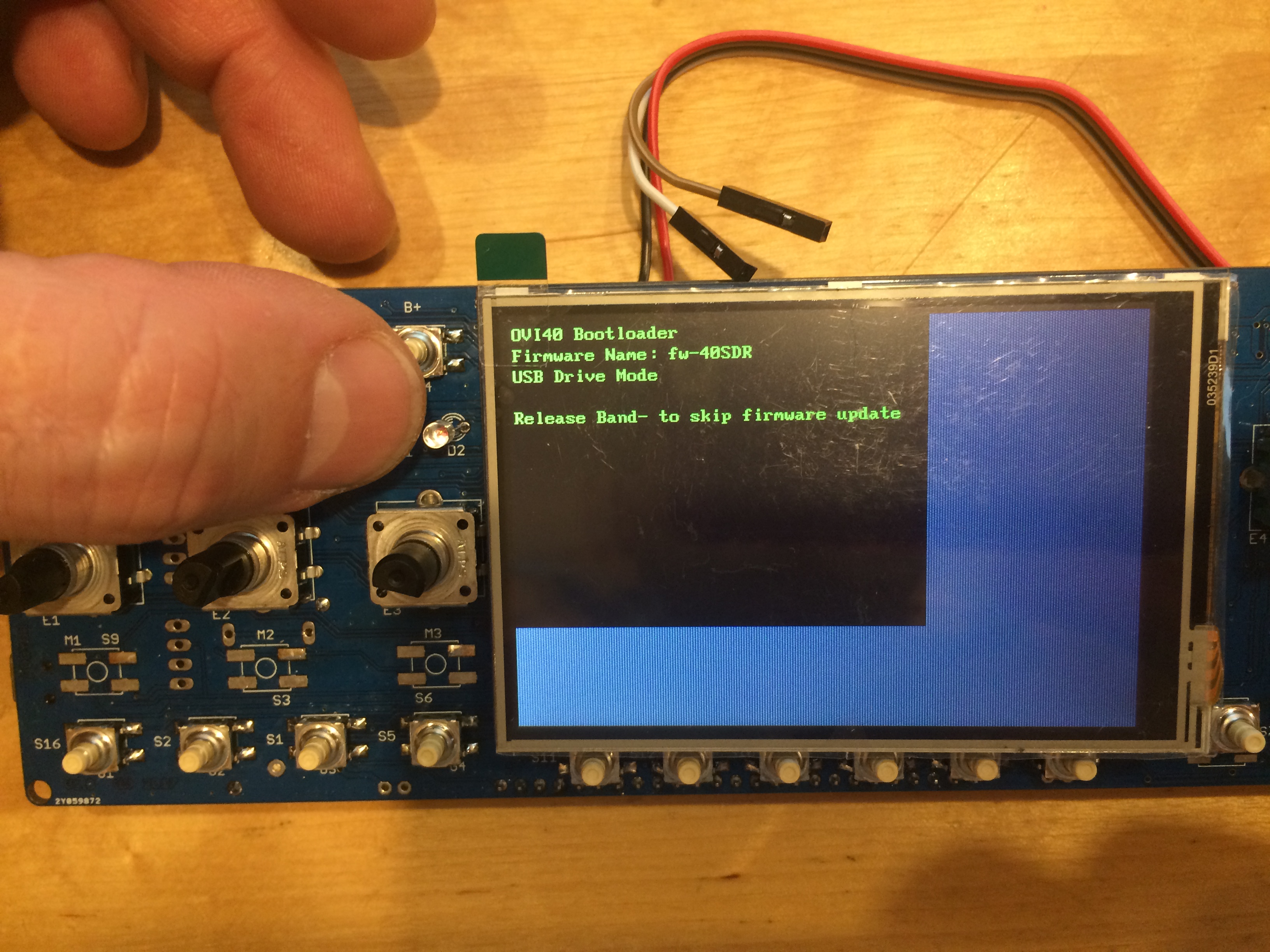
I am now stuck when trying to upload the firmware fw-40SDR.bin
- the firmware is on a USB stick, plugged into the USB socket
- I apply power while keeping pressed the Band- button
- I release the button when the green led light up (flashing)
and then nothing more...
I was wondering about the R101 resistor. The schematics says "option for 24LC1025". Should it be fitted with the ATMLH746 I got ?
Best Regards,
François
|
|
|
|
|
|
F4HTX
schon länger dabei
Offline
Posts: 66
Scotty, energize...
|
|
Re:Aufbaubericht OVI40-UI Platine Version 1.8
« Reply #18 on: 10. January 2018, 16:02:34 »
|
|
Dear Friends,
Everyone keep on soldering obviously, the forum is deserted...
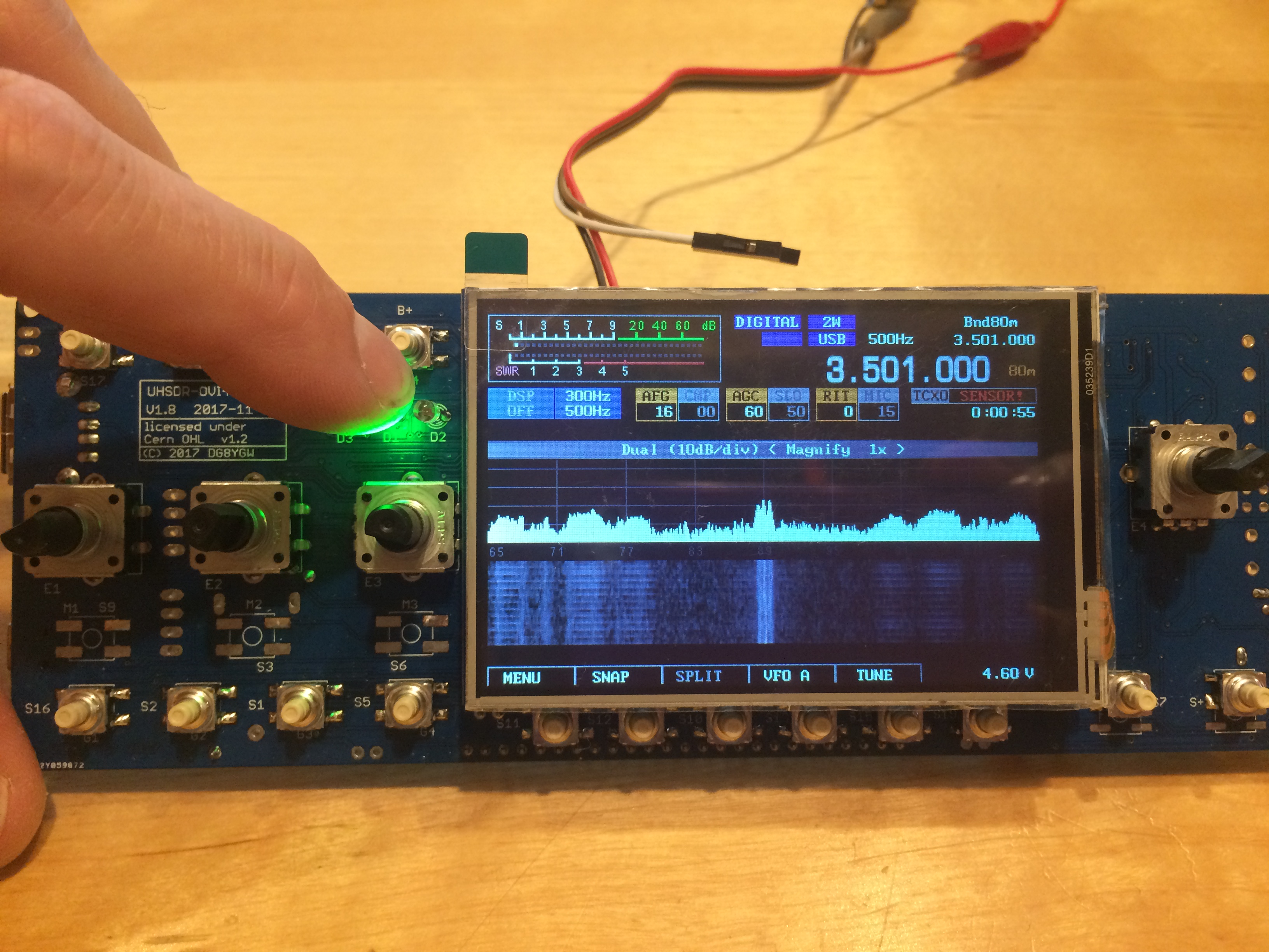
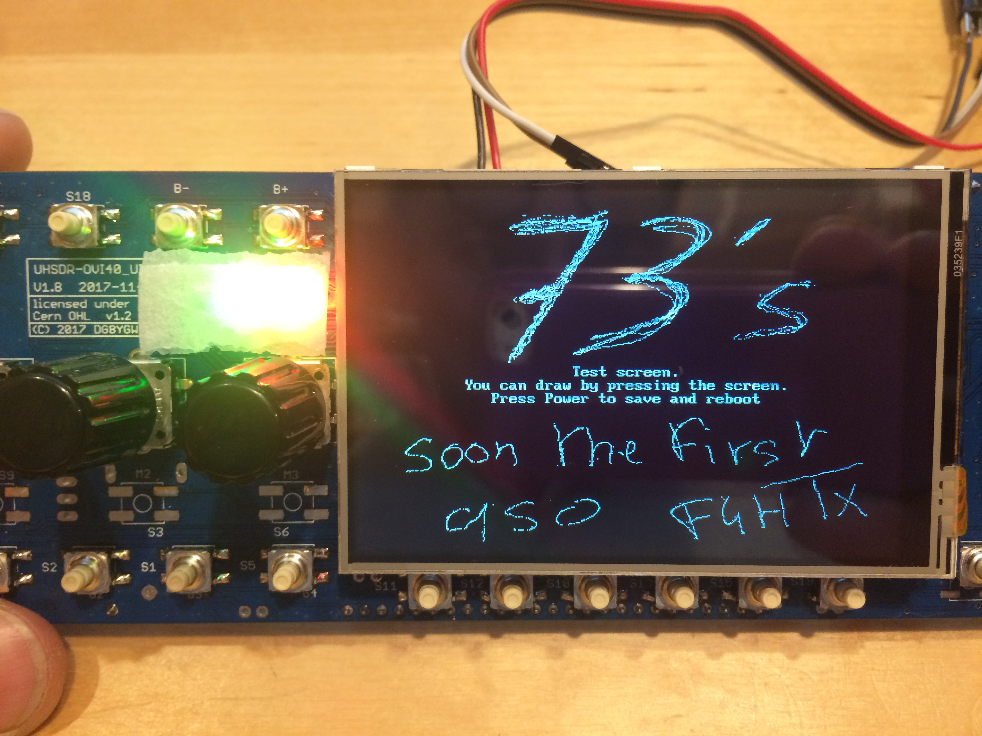
I uploaded the firmware via DFU and it did work. There are still some issues to fix :
- the touchscreen controller is not detected
- the USB firmware upgrade still unsuccessful
I will start by another detailed eye checking of the board, for sure I missed something.
But overall it's a success, the OVI-40 v1.8 kit is close to perfect, reasonably easy to populate.
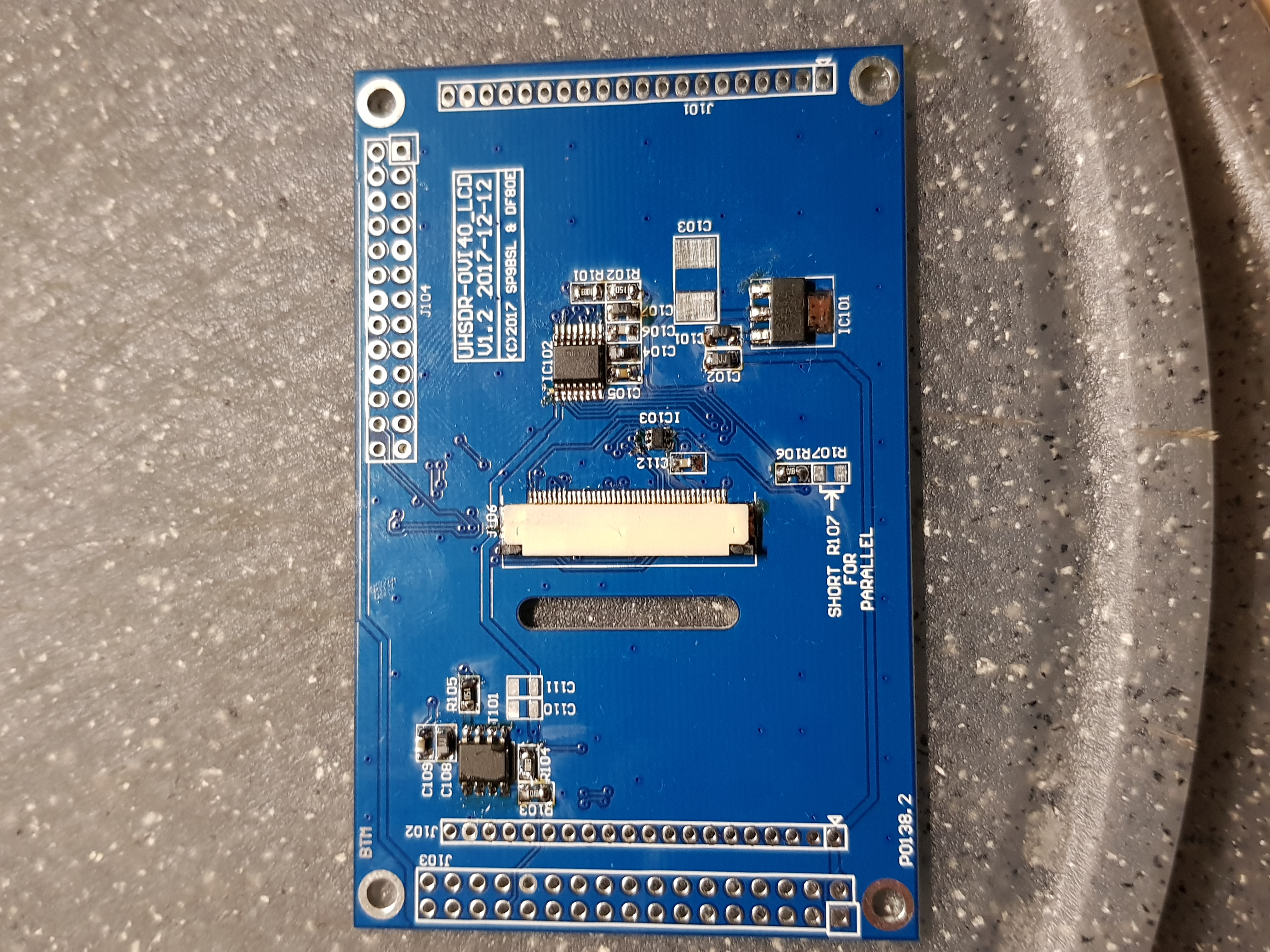
About the placement of the components, I did a scan of the pcb and printed it as large as possible in black and white. Easy to locate the components then.
73's
François / F4HTX
|
 IMG_1956.JPG IMG_1956.JPG
« Last Edit: 10. January 2018, 16:07:27 by F4HTX » |
 Logged Logged
|
|
|
|
db9mat
noch länger dabei
Offline
Posts: 104
Ich liebe dieses Forum!

|
|
Re:Aufbaubericht OVI40-UI Platine Version 1.8
« Reply #19 on: 10. January 2018, 16:28:13 »
|
|
Habt ihr das LCD irgendwie an der Platine befestigt oder hängt das auch noch am Flachbandkabel, bis es irgendwann nicht mehr dran hängt? 
|
|
Logged
|
|
|
|
dg0nf
OM_nicht_I40
noch länger dabei
Offline
Posts: 133
OV V30 - Wolgast/Insel Usedom
|
|
Re:Aufbaubericht OVI40-UI Platine Version 1.8
« Reply #20 on: 10. January 2018, 16:36:22 »
|
|
Gratulation zum Funktionierenden Board. Ich bin abgelenkt worden (muss ja nebenbei auch bissel arbeiten) und bin immer noch beim passiven Kram. Aber viel ist nicht mehr. Dann geht es mit Aktiv weiter. Wird aber sicher erst morgen...
Eine Frage habe ich: Bei mir waren in der Tüte 5 anstelle der 1µF-Cs in 0603 die Cs in 1206 drin. Ich löte ja 0805 auf Pads von 0603 ohne zu murren, aber 1206 auf 0603 passt irgendwie nicht so richtig. Ist das bei Anderen auch so? Ich meine, ist für mich kein Problem, ich greife in die Kiste und hab die Dinger in 0603 da, aber hat ja nicht jeder so ein gut sortiertes Lager...
Die beiden Cs für den Quarz (Tüte 6) haben 0402, die kann man aber problemlos auf 0603-Pads löten (wie auch 0603 problemlos auf 0805 passt)...
|
|
Logged
|
|
|
|
dg0nf
OM_nicht_I40
noch länger dabei
Offline
Posts: 133
OV V30 - Wolgast/Insel Usedom
|
|
Re:Aufbaubericht OVI40-UI Platine Version 1.8
« Reply #21 on: 10. January 2018, 16:44:17 »
|
|
Hast Du die aufgelötet? 
|
|
Logged
|
|
|
|
db9mat
noch länger dabei
Offline
Posts: 104
Ich liebe dieses Forum!
|
|
Re:Aufbaubericht OVI40-UI Platine Version 1.8
« Reply #22 on: 10. January 2018, 16:53:12 »
|
|
das wird noch mit dünnem, doppelseitigem Klebeband befestigt.
Machen die bei den Massenprodukten für Raspberry Pi und Co übrigens ganz genauso
|
|
Alles klar. Dann so, dass der DIL-Pinheader frei bleibt und das LCD auf der anderen seite etwas übersteht denke ich?
und bloß nicht am Folienleiter baumeln lassen....der ist ruck zuck kaputt und somit das TFT für die Mülltonne.
|
|
Ja.. deswegen frage ich 
|
|
Logged
|
|
|
|
F4HTX
schon länger dabei
Offline
Posts: 66
Scotty, energize...
|
|
Re:Aufbaubericht OVI40-UI Platine Version 1.8
« Reply #23 on: 10. January 2018, 18:07:34 »
|
|
Dear Friends,
My feedback about the building of my first v1.8 OVI-40 UI
Components :
- I got 8x 1µF COG 0805 instead of 0603. The pads are too small for a reliable setting of the 0805 caps, so I changed the caps for 10µF 0603 I had in stock. I’ll re-change them later for the initial value and COG caps.
- as I mentioned earlier the mini USB socket doesn’t work, so please check it out before soldering.
- the 3x 3,5mm jacks do not fit on the pcbs, the two setting fingers are not in the same position. You might cut them out, but as there are mechanical efforts on these parts, I’d rather swap them for the correct one.
Everything else worked fine for me. I attached a file with the who’s who of the small parts. I hope this helps.
I still have some issues, I’ll share later, when solved.
Have fun !!!
François
|
|
|
|
|
SP9BSL
positron
alter Hase
Offline
Posts: 443

|
|
Re:Aufbaubericht OVI40-UI Platine Version 1.8
« Reply #24 on: 10. January 2018, 18:10:05 »
|
|
Hi everyone,
congratulations with working boards!
@Thomas: I'm glad that your touch works, you know- I was quite stressed - not much like Andreas but also
Regarding the ZIF (FPC) connector: this footprint was precisely redrawn from Molex datasheet as recommended, which is the source for all China cloners. I still wait for lcds and connectors and will investigate where is the problem when they arrive. There will be next revision of lcd board when we finally run the SPI for this lcd. As Andreas said there is a mismatch with the datasheet of ILI9486 and reality. Enjoy the new look and feel of this rig. We take deep breath now and prepare new goodies 
|
| « Last Edit: 10. January 2018, 18:12:54 by SP9BSL » |
Logged
|
73 Slawek
|
|
|
dl2eea
schon länger dabei
Offline
Posts: 59
Ich liebe meine Frau!
|
|
Re:Aufbaubericht OVI40-UI Platine Version 1.8
« Reply #25 on: 10. January 2018, 18:37:32 »
|
|
Hallo an ale,
Läst sich das 3,5 Display Dimmen?
73 Josef
|
| « Last Edit: 10. January 2018, 18:38:21 by dl2eea » |
Logged
|
|
|
|
F4HTX
schon länger dabei
Offline
Posts: 66
Scotty, energize...
|
|
Re:Aufbaubericht OVI40-UI Platine Version 1.8
« Reply #26 on: 10. January 2018, 18:58:33 »
|
|
Dear Friends,
One LCD fixed. Fascinating !!!
I gotta buy shades to bear those led's 
73's Thomas 73's Slawek and 73's Andreas indeed
François
|
|
|
|
DF9EH
alter Hase
Offline
Posts: 284
|
|
Re:Aufbaubericht OVI40-UI Platine Version 1.8
« Reply #27 on: 10. January 2018, 21:37:06 »
|
|
Hallo zusammen,
bei der nicht passenden USB Buchse dürfte es sich um die USB MINI-A Version handeln.
|
|
Logged
|
73 de Klaus
|
|
|
DL9CHR
schon länger dabei
Offline
Posts: 66
vy 73!
|
|
Re:Aufbaubericht OVI40-UI Platine Version 1.8
« Reply #28 on: 11. January 2018, 06:46:56 »
|
|
Servus zusammen,
mal eine ganz blöde Frage... Wo finde ich den Bestückungsplan der Display-Platine?
Danke, vy 73!
Christoph
|
|
Logged
|
|
|
|
Michael_K
Urgestein
Offline
Posts: 638
Ich liebe dieses Forum!
|
|
Re:Aufbaubericht OVI40-UI Platine Version 1.8
« Reply #29 on: 11. January 2018, 06:58:15 »
|
|
@Christoph,
war irgendwo im Forum veröffentlicht (Anhang)
vy 73 aus Erfurt
Michael_K
PS: einfach ausdrucken, ist gut lesbar
EDIT bei Mod: Achtung, im Bild sind die meisten 10µF Tantal Elkos falsch rum bestückt!!
|
|
|
|
|
|
|