Pages: 1 2 [3] 4 
|
 |
|
|
 Author
|
Topic: LCD 3.5" DF8OE/SP9BSL (Read 16991 times)
|
|
Michael_K
Urgestein

 Offline Offline
Posts: 638

Ich liebe dieses Forum!

|
 |
Re:LCD 3.5" DF8OE/SP9BSL/Position LCD
« Reply #30 on: 18. January 2018, 05:05:02 »
|
|
Hier mal eine Frage "mechanischer" Natur:
da ja das LCD dank der Flexbandleitung ein paar mm hin und her geschoben werden kann, wo positionieren wir das Teil auf der Träger-/Adapter-Platine?
Das hat aktuell eine geringe Bedeutung, aber später für die Frontplattengestaltung (Durchbruch zum Display) für die "allgemeine Nachnutzung" der Zeichnungen doch.
Vielleicht kann Andreas diese Frage an Hand der "fertig konfektionierten" Displays beantworten.
vy 73 aus Erfurt
Michael_K
|
|
 Logged Logged
|
|
|
|
|
|
Paul C. H.
Neuling
Offline
Posts: 23
Ich liebe dieses Forum!
|
|
Re:LCD 3.5" DF8OE/SP9BSL
« Reply #32 on: 21. January 2018, 19:49:18 »
|
|
Is XPT2046 equivalent for ADS7843E? I soldered it already.
but I don't know if XPT works or not, because I made another mistake.
I ordered bare boards of OVI40 and buy my own components (coz I have some stored value in a local online component shop). I ordered the wrong FPC40 connector so that I need to wait for the correct one.
For those who are planning to order their own component: be aware some FPC40 connectors have metal contacts under the cable, some have metal contacts on top of the flat cable. I think top-contact type is correct.
|
|
Logged
|
I understand only two German words.
with help of this forum, I often change from "g-e-t-l-o-s-t" to "g-e-l-ö-s-t".
what in front of me was feeling of "f-u-n-k", now it is a piece of almost working "f-u-n-k"
|
|
|
|
|
Paul C. H.
Neuling
Offline
Posts: 23
Ich liebe dieses Forum!
|
|
Re:LCD 3.5" DF8OE/SP9BSL
« Reply #34 on: 23. January 2018, 08:30:53 »
|
|
No luck (yet) after replacement of FPC connector (from botton-contact to top-contact)
Going to do a open-short test (drafted a diagram for test-points but cannot upload attachment)
If I use a HY32D-ILI LCD instead, do I need modification of anything? (other than loading low-resolution firmware) I maybe able to get HY32D delivered tomorrow.
Paul
|
| « Last Edit: 23. January 2018, 16:06:34 by Paul C. H. » |
Logged
|
I understand only two German words.
with help of this forum, I often change from "g-e-t-l-o-s-t" to "g-e-l-ö-s-t".
what in front of me was feeling of "f-u-n-k", now it is a piece of almost working "f-u-n-k"
|
|
|
Paul C. H.
Neuling
Offline
Posts: 23
Ich liebe dieses Forum!
|
|
Re:LCD 3.5" DF8OE/SP9BSL
« Reply #35 on: 23. January 2018, 09:44:39 »
|
|
Thanks
Yes, grounded LCD_cfg with R107=0R, omitted the pullup R106 as well.
Short pin 3,4 of smallest IC footprints.
Not yet cut SPI_SDO as I assume it is not a cause of white-screen.
Paul.
Paul,
very important: R107 = 0R ?
|
|
|
|
Logged
|
I understand only two German words.
with help of this forum, I often change from "g-e-t-l-o-s-t" to "g-e-l-ö-s-t".
what in front of me was feeling of "f-u-n-k", now it is a piece of almost working "f-u-n-k"
|
|
|
|
|
Paul C. H.
Neuling
Offline
Posts: 23
Ich liebe dieses Forum!
|
|
Re:LCD 3.5" DF8OE/SP9BSL
« Reply #37 on: 23. January 2018, 16:10:50 »
|
|
Thanks Andreas.
When I post my question, I thought of adding a remark "Andreas - do not answer, I read from forum knowing you are sleeping 4 hours/day", other OM can help. This is hobby, nothing urgent.
and I have 6 hours sleep per day after busy debugging.
|
|
Logged
|
I understand only two German words.
with help of this forum, I often change from "g-e-t-l-o-s-t" to "g-e-l-ö-s-t".
what in front of me was feeling of "f-u-n-k", now it is a piece of almost working "f-u-n-k"
|
|
|
Paul C. H.
Neuling
Offline
Posts: 23
Ich liebe dieses Forum!
|
 |
STUPID MISTAKE
« Reply #38 on: 23. January 2018, 16:49:27 »
|
|
I made sketch on printout of LCD-PCB, marked test-points with connected FPC pin numbers (1 to 40) for debugging.
After an hour of open-short test, re-checking, re-re-checking, I confirm there is no short to adjacent pins at FPC (beep test). Used ohm meter to check connectivity across each signal lines to GND, all confirmed there are not short to GND (0 ohm) or disconnected (ohm meter don't move) - assume no known problem with LCD-PCB
I did the same signal lines to GND test at the UI board 34 pin LCD connector , except NC pins, all confirmed connectivity to the mCU. RX LED on UI board will flash if power on with B- (bootloader USB firmware update mode)
I assume no known problem with UI board.
THEN, I FOUND MYSELF A STUPID MISTAKE.
I soldered the 34 pin block connector only at the LCD-PCB side, assuming the holes on UI-PCB are small and tight enough, pins will connect by insert without solder. This assumption is correct when I work on other projects with 8 or 10 pins. But when check with multimeter, it is not the case, a few signal lines doesn't connect.
The reason I made this very STIPID mistakes is:
1. in case thing doesn't work, it take substantial long time to de-solder 34 pins.
2. if I add a female socket on the UI-PCB, the LCD-PCB will be at least 9mm away, will not fit in existing mcHF enclosure.
Is there better method to confirm the LCD works, without soldering both side of 34 pin block connector?
(or any male-female connector not 9mm thick?)
Paul
|
|
Logged
|
I understand only two German words.
with help of this forum, I often change from "g-e-t-l-o-s-t" to "g-e-l-ö-s-t".
what in front of me was feeling of "f-u-n-k", now it is a piece of almost working "f-u-n-k"
|
|
|
|
|
Paul C. H.
Neuling
Offline
Posts: 23
Ich liebe dieses Forum!
|
|
Re:LCD 3.5" DF8OE/SP9BSL
« Reply #40 on: 24. January 2018, 11:05:11 »
|
|
Regarding headers:
For compatibility reasons I recommend to put the female header on UI PCB. There exist some with a height of 5mm - these are the best. At LCD you must fit the male header. You can shorten the pins to a length of 3...4mmm so that LCD PCB is directly laying on female header.
vy 73
Andreas
|
|
found 5mm female header, minimal order quantity is 1000, but I am lucky enough as the seller gave me a free sample :- broken piece of a longer header with 23x2. Okay to use if trim to 17x2, haha.
I think 5mm header is must. Let's think of a mcHF with LCD 10mm above the UI, it is very difficult to design the metal case.
Also, received my 3.2inch LCD today. Thanks.
Paul
|
| « Last Edit: 24. January 2018, 11:17:53 by Paul C. H. » |
Logged
|
I understand only two German words.
with help of this forum, I often change from "g-e-t-l-o-s-t" to "g-e-l-ö-s-t".
what in front of me was feeling of "f-u-n-k", now it is a piece of almost working "f-u-n-k"
|
|
|
|
|
Paul C. H.
Neuling
Offline
Posts: 23
Ich liebe dieses Forum!
|
|
Re:LCD 3.5" DF8OE/SP9BSL
« Reply #42 on: 24. January 2018, 15:44:11 »
|
|
Yes, 5mm is mandatory. Using this header button caps are ~2mm off the case and encoder knobs do fit. Here in Germany you can buy these headers i 1pcs. amounts.
I am astonished that it is difficult in China! I thought China is the paradise for DIY...
vy 73
Andreas
|
|
Yes, easy and difficult!
9mm headers are easy to find. I asked approximately 7 or 8 sellers and only 2 provides 5mm header.
Sellers here keep samples of many products in a very small stall of only 1 square meter.
They are reluctant to retail sell their samples, and leave enough samples available for big-deal customers, hope if you or Chris go there and order one container of parts.
The 3.5" LCD actually works. It didn't work yesterday only because of my wrong assumption (no solder temporary connection)
Paul
|
|
Logged
|
I understand only two German words.
with help of this forum, I often change from "g-e-t-l-o-s-t" to "g-e-l-ö-s-t".
what in front of me was feeling of "f-u-n-k", now it is a piece of almost working "f-u-n-k"
|
|
|
F4HTX
schon länger dabei
Offline
Posts: 66
Scotty, energize...
|
|
Re:LCD 3.5" DF8OE/SP9BSL
« Reply #43 on: 18. February 2018, 11:06:49 »
|
|
Dear Friends,
I am not sure where to post this, but anyway you might like this one...
After a couple weeks overhelmed by pro, I came back to my OVI-40 UI board, so I plugged it in, updated the bootloader and the firmware.
When I rebooted I was asked to calibrate the touchscreen, no problem it was expected but... impossible to enter the calibration screen, no way !
The touchscreen IC showed up in the menus, but no touchscreen working (it was working in the first place indeed).
I spent a significant amount of time searching the cause, finally here the story :
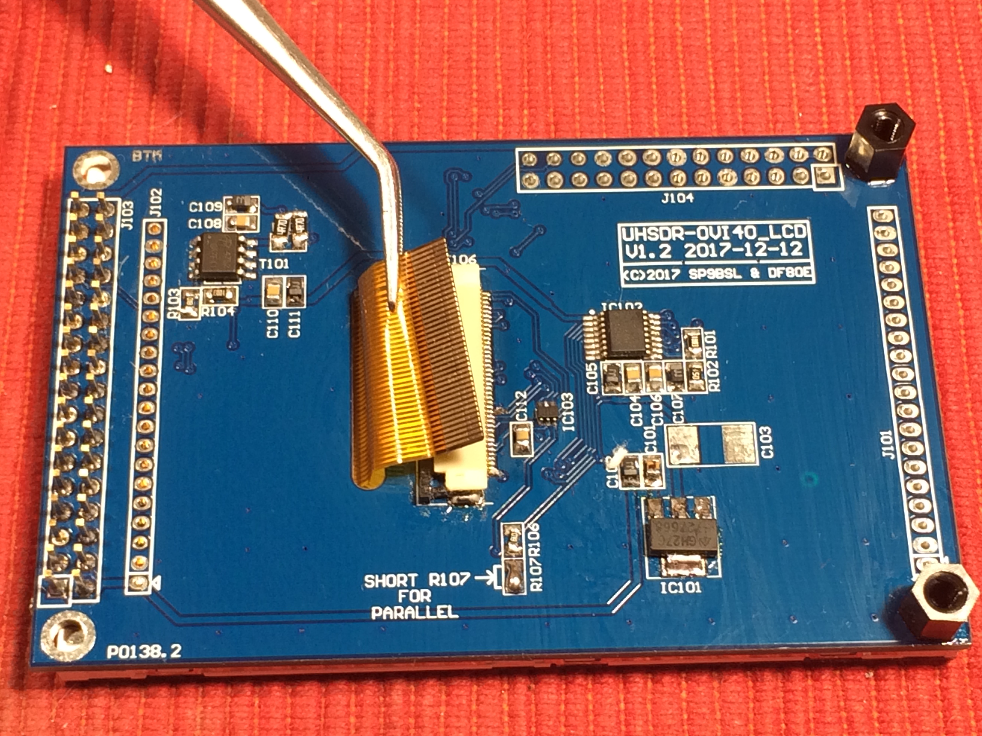
I got very early birds of the production of those screens, with the sdo line and some components in the wrong orientation (Andreas, even Spock sleeps from time to time  ). In order the straighten things, I unpopulated then repopulated the boards, cleaned it (isopropyl alcohol) and everything went fine. ). In order the straighten things, I unpopulated then repopulated the boards, cleaned it (isopropyl alcohol) and everything went fine.
But... when cleaning with isopropyl, a mix of it with the cleaned flux entered the J106 connector and after a couple weeks, the connections becamed unreliable.
I cleaned the connector and the ribbon, let both of them dry and... tada!!!
So when you clean things, you should beware of connectors, encoders, plugs, ...
73's
François
|
|
|
|
SP9BSL
positron
alter Hase
Offline
Posts: 443

|
|
Re:LCD 3.5" DF8OE/SP9BSL
« Reply #44 on: 18. February 2018, 12:04:44 »
|
|
Hi François,
yes, this is often problem with dirt in connectors came from soldering, especially with the one you can't see (inside of the J106). Be aware of the pins of J103 also, I had problems with 2.54 conector too. I know this pain, spent about an hour seeking what is wrong... Isopropyl solvent is the good helper.
|
|
Logged
|
73 Slawek
|
|
|
Pages: 1 2 [3] 4 
|
|
|
|
|
|
|


 Firstly RF-PCB must be ready and some other work must be done - then designing of cases will start.