df9ts
positron
schon länger dabei

 Offline Offline
Posts: 73

Ich liebe dieses Forum!

|
 |
Re:Aufbaubericht OVI40-UI Platine Version 1.8
« Reply #90 on: 22. January 2018, 20:45:07 »
|
|
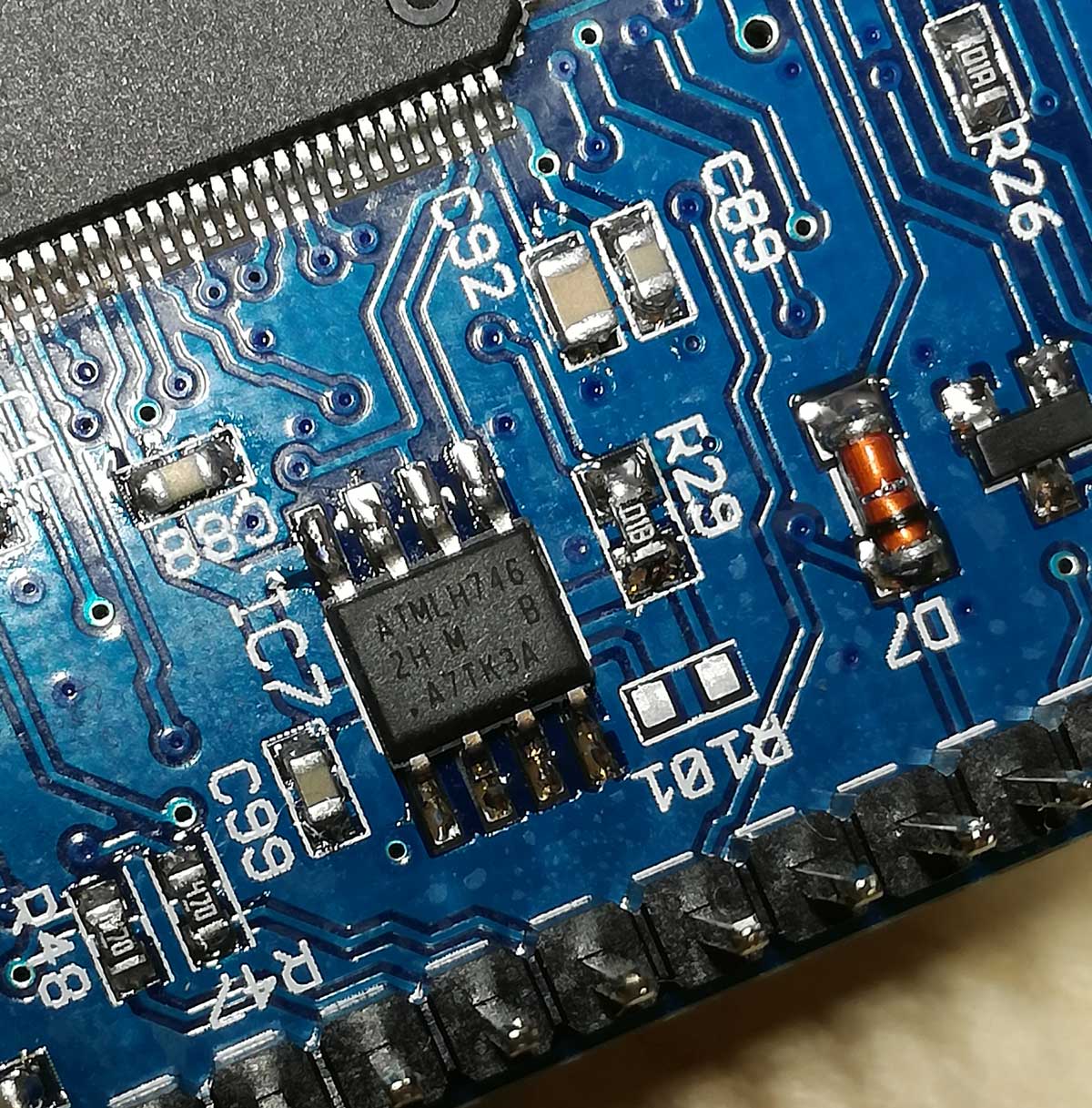
IC7 AT24CM02 EEPROM - wo ist Pin 1 
Wie ist denn der Pin1 markiert? Finde keinen Punkt auf dem Gehäuse, auch keine schräge Ecke?
ATMLH746
2H M B
.AT7k3A
Ist vielleicht der Punkt (der aussieht wie ein Teil der Beschriftung) der Pin 1?
73
Gerd.
|
|
 Logged Logged
|
|
|
|
|
|
DF9EH
alter Hase
Offline
Posts: 284
|
|
Re:Aufbaubericht OVI40-UI Platine Version 1.8
« Reply #92 on: 22. January 2018, 21:19:52 »
|
|
Hallo Gerd,
da ist ein kleiner Punkt 
Und eine Schräge ......
|
73 de Klaus
|
|
|
df9ts
positron
schon länger dabei
Offline
Posts: 73
Ich liebe dieses Forum!
|
|
Re:Aufbaubericht OVI40-UI Platine Version 1.8
« Reply #93 on: 22. January 2018, 21:29:23 »
|
|
Vielen Dank!
|
|
Logged
|
|
|
|
G4KCM
Neuling
Offline
Posts: 24

|
|
Re:Aufbaubericht OVI40-UI Platine Version 1.8
« Reply #94 on: 01. February 2018, 10:03:35 »
|
|
Construction complete, I have no new comment to add other than to echo the remarks previously made regarding component sizes. There seems to be plenty of ‘real estate’ on the PCB so it would be good to standardise on larger component sizes where possible.
The kit was complete and correct and ingeniously packed which along with the searchable layout pdf made the location of components quite easy. The only thing I needed to substitute was the mini USB which I already had in my component stock.
Have checked all that I can and the micro controller enters DFU mode so now the H7 patientialy awaits the firmware. If there is a ‘test’ load available I would be happy to try it.
Thank you to the team for the efforts in the development and documentation.
73
Clive
|
|
Logged
|
|
|
|
Co
schon länger dabei
Offline
Posts: 79
Ich liebe dieses Forum!
|
|
Re:Aufbaubericht OVI40-UI Platine Version 1.8
« Reply #95 on: 03. February 2018, 12:16:20 »
|
|
Hi Andreas,
Finished assembly UI board V1.08 this morning. Loaded bootloader and firmware 2.7.87 and bingo first try. No new problems encountered apart from those already reported.
Would also recommend switching to smd size 0805 to raise the fun level while assembling. Well done developers
73's
Co
|
|
Logged
|
|
|
|
sm0nor
schon länger dabei
Offline
Posts: 61
Ich liebe dieses Forum!
|
|
Re:Aufbaubericht OVI40-UI Platine Version 1.8
« Reply #96 on: 04. February 2018, 12:55:51 »
|
|
Hi all!
First time SMD soldering :-). Works fine (of course I have done normal soldering for 40 years).
I'm about 20% done, so a long way to go still  . I'm still trying to figure out the best soldering tip to use. I have half a dozen of tips to my 1970's Weller Magnastat. P06, P07, P08 in various shapes and sizes. It seem the "bigger" ones, ca 1,2mm, are easier to work with than the smaller ones. But I'm still applying to much solder in my opinion.. . I'm still trying to figure out the best soldering tip to use. I have half a dozen of tips to my 1970's Weller Magnastat. P06, P07, P08 in various shapes and sizes. It seem the "bigger" ones, ca 1,2mm, are easier to work with than the smaller ones. But I'm still applying to much solder in my opinion..
What are your favourite tips? Temperature?
73's Ulf SM0NOR
|
| « Last Edit: 04. February 2018, 12:57:00 by sm0nor » |
Logged
|
|
|
|
db9mat
noch länger dabei
Offline
Posts: 104
Ich liebe dieses Forum!
|
|
Re:Aufbaubericht OVI40-UI Platine Version 1.8
« Reply #97 on: 04. February 2018, 18:16:11 »
|
|
400°C is _way_ too much, especially for leaded solder.. 340 is more than enough
|
|
Logged
|
|
|
|
sm0nor
schon länger dabei
Offline
Posts: 61
Ich liebe dieses Forum!
|
|
Re:Aufbaubericht OVI40-UI Platine Version 1.8
« Reply #98 on: 09. February 2018, 21:33:58 »
|
|
Hi All!
Everything goes well here. A bit slow, but I'm in no rush.
I just wonder how I solder the TXCO IC5? Will the solder flow in under the IC and make connection? I mean it is hard to see if it has connected since the pads are under it. Tried to google a bit but didn't find anything useful. Is there a way to check if it has made connection?
73's
Ulf SM0NOR
|
|
Logged
|
|
|
|
sm0nor
schon länger dabei
Offline
Posts: 61
Ich liebe dieses Forum!
|
|
Re:Aufbaubericht OVI40-UI Platine Version 1.8
« Reply #99 on: 10. February 2018, 07:56:24 »
|
|
Hi All!
Everything goes well here. A bit slow, but I'm in no rush.
I just wonder how I solder the TXCO IC5? Will the solder flow in under the IC and make connection? I mean it is hard to see if it has connected since the pads are under it. Tried to google a bit but didn't find anything useful. Is there a way to check if it has made connection?
|
|
Got it! I found the answer myself by reading the thread about hot air station. I will purchase el cheapo this week.
73's
Ulf SM0NOR
|
|
Logged
|
|
|
|
SP9BSL
positron
alter Hase
Offline
Posts: 443

|
|
Re:Aufbaubericht OVI40-UI Platine Version 1.8
« Reply #100 on: 10. February 2018, 08:40:27 »
|
|
I will purchase el cheapo this week.
|
|
This is good, have to add it to my best sentences list 
Good decision anyway.
|
|
Logged
|
73 Slawek
|
|
|
df9ts
positron
schon länger dabei
Offline
Posts: 73
Ich liebe dieses Forum!
|
|
Re:Aufbaubericht OVI40-UI Platine Version 1.8
« Reply #101 on: 10. February 2018, 09:52:12 »
|
|
TXCO can be solder with normal tip.
Tin-coating the TXCO pins and PCB pads helps, remove most of it with solder wick, then apply flux.
Solder TXCO in by heating up the PCB pads, heat will go under the TXCO. Worked on two UI boards.
El cheapo..
Anyway hot air is nice to have.
Gerd.
|
|
Logged
|
|
|
|
|
|
DL4HAO_Dietmar
Neuling
Offline
Posts: 11

|
|
Re:Aufbaubericht OVI40-UI Platine Version 1.8
« Reply #103 on: 14. February 2018, 11:29:50 »
|
|
Hallo zusammen!
Da ich aktuell ein paar Tage Urlaub habe, kam die Zusendung des Bausatzes gerade richtig (Sammelbestellung von Jürgen, DD2XJ). Danke!
Ich bin nun bei Beutel 3 und finde dort einen 8-Beiner (ist wohl ein SO08 Gehäuse) mit dem Aufdruck (obere Reihe) ATMLH746 in der mittleren Reihe steht 2H M B und in der unteren Reihe steht .A7TK3A
Welches IC ist das denn? Ist das ein Ersatz für IC7 AT24CM02, ein I2C EEPROM?
In der Packliste für Beutel 3 finde ich nicht die Bezeichnung dieses Bauteils, auch nicht, dass das IC7 sein soll. In der gesamten Packliste finde ich die Bennenung der Bauteile nicht, also welches Bauteil denn in Beutel 3 nun Diode-X oder IC-Y oder Transistor-Z ist.
Ist mein ATMLH746 nun dieses IC7 AT24CM02?
In dem Errata habe ich für Beutel 3 keinen Eintrag gefunden.
vy73
Dietmar, DL4HAO
|
|
Logged
|
Große Geister unterhalten sich über Ideen, Durchschnittsmenschen über Ereignisse und kleine Leute über andere. (Sokrates)
|
|
|
|
|


 Author


