UHSDR Troubleshooting
LCD constant white screen
In case the LCD remains white (background light on, no text) after OVI40 UI power up this indicates
- no UHSDR boot loader present or
- UHSDR boot loader doesn't work properly
The correct UHSDR functioning can be verified with simple means:
- If the LCD flickers bright white when switching OVI40 UI on this indicates a bootloader present and working
- Press and keep pressed switch “Band +”, then apply +5V to OVI40 UI. Text should appear on LCD.
- Press and keep pressed switch “Band -”, then apply +5V to OVI40 UI. Text should appear on LCD.
If this is not the case the boot loader needs to be (re)installed (see below). If this still doesn't solve the issue please check for possible hardware errors (see below).
MCU "bricked"
If there is no hardware defect it may help to re-install boot loader and firmware:
In case ST-Link/V2 available
A non-functional MCU may be restored - if there is no hardware problem - with the ST-Link/V2 adapter and the required .bin file. The file can be found here.
You will need:
- STM32 ST-Link SW utility
- Neueste Bootloader und UHSDR Firmware (.bin files)
1. Preconditions
- STlink software installed
- ST-Link/V2 adapter connected
- PC connected to Internet
2. ST-Link/V2 Firmware updateProcedure
- Connect ST-Link/V2 with PC via USB cable
- SW Utility: ST-Link→Firmware update
- Check on PC screen in status messages that MCU is reckognized correctly
3. Debug cable
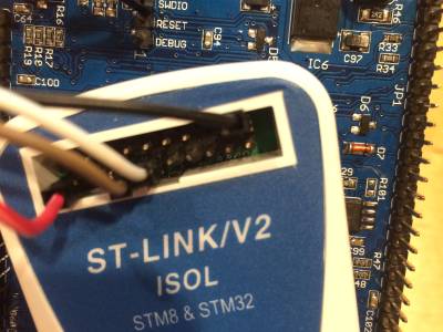
The debug cable shouldn't be longer than 10 cm. 3 to 4 connections are needed.
| ST-link adapter | OVI40 UI JP8 | Remark |
| Pin-13 TRACESWO | JP8 Pin 1 | Debug Output |
| Pin-15 NRST | JP8 Pin 2 | Reset |
| Pin-07 SWDIO | JP8 Pin 3 | Debug I/O |
| Pin-09 SWCLK | JP8 Pin 4 | Debug Clock |
| Pin-01 MCU VDD | JP8 Pin 5 | VDD from MCU |
| Pin-20 Gnd | JP8 Pin 6 | Ground |
4. Connect
- SW Utility: Target→Connect
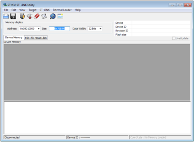
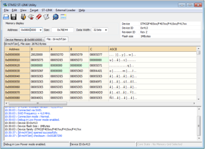
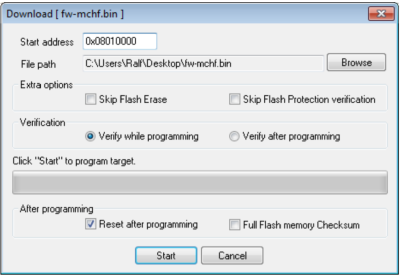
- SW Utility: File → Open (select the right .bin file, see above). The following screen should appear: (example shows mcHF boot loader)
5. Flash the MCU
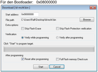
- Write the .bin file onto MCU with Target → Program & Verify
- In the subsequent windo enter start address:
- start adresse for boot loader: 0x08000000
- Then hit start button to program MCU
- Then program firware in the same manner.
- start address for firm ware would be 0x08010000
6. Done
Boot loader and firmware are now programmed again onto MCU.
Restore MCU Option bytes
1. You will need the ST-Link Tool. No account required, just provide valid e-mail - download link will be sent to this e-mail.
2. Connect ST-LINK USB (3 Leitung SWDIO, SWCLK und GND) with the corresponding pins of OVI40 UI (adapter cable see above).
3. Apply +5V to OVI40 UI, then in SW tool click Target→Connect. The MCU should be recognized, see status messages on screen. Otherwise re-check cables.
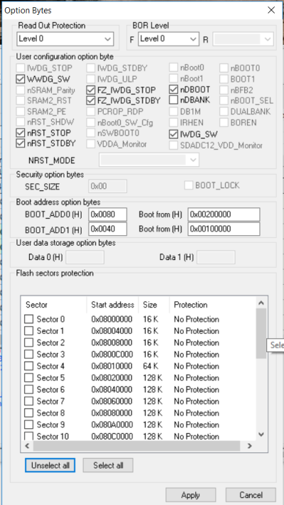
4. If ok in SW tool click Target→MCU Core to display MCU option bytes.
These are the correct values:
| Read Out Protection: | Level0 |
| BOR-Level: | Level3 |
| IWDG_SW: | gesetzt |
| WWDG_SW: | gesetzt |
| nRST_STOP: | gesetzt |
| nRST_STDBY: | gesetzt |
| FZ_IWDG_STOP: | gesetzt |
| FZ_IWDG_STDBY: | gesetzt |
| nDBOOT: | gesetzt |
| nDBANK: | nicht gesetzt |
| BOOT_ADD0: | 0x0080 Boot from 0x200000 |
| BOOT_ADD1: | 0x0040 Boot from 0x100000 |
| No ticks set at all in any box below “Flash Section Protection” |
SW Bugs in boot loader or firmware
The list of open issues can be found here.
- Also interesting to check list of closed issues.
- If not found in open or closed issues please discuss on forum - it may not be a SW error at all, so better verify
- In case you think you discovered a bug not mentioned yet:
- Please post as new issue in Github. Add additional info as comment, if diiscovered later.
- Please be patient. All Github members work on this in their free spare time
Check for defective hardware
- Has MCU be soldered in with correct Pin1 orientation?
- +3.3V available for MCU? Ground available?
- TCXO clock available?
- All connections from MCU to USB ports ok - no shurtcuts, no interruptions?
